Painted steel exteriors carry a century of accumulated compromise: energy-hungry paint shops, multi-die stamping capital, corrosion and weight. What follows is the process that replaces them, the two material platforms it runs on, and the test data behind both.
Four steps. One cell. Zero paint.
Press, body, paint and assembly are four plants in series. The forming cell is one machine: a sheet that already carries its colour goes in, a finished structural panel comes out, and nothing in between leaves the cell.
01
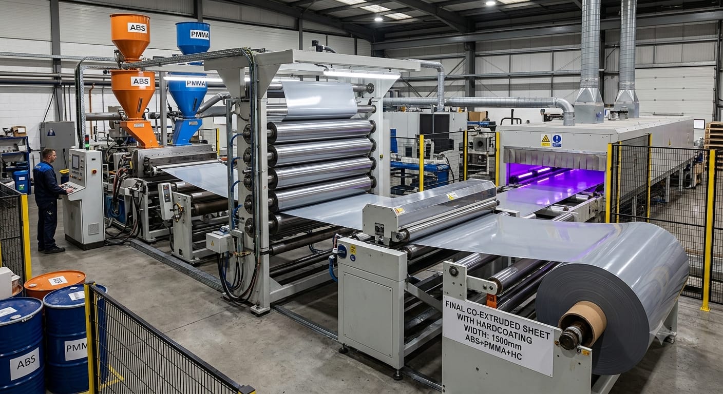
Multi-layer co-extruded sheet
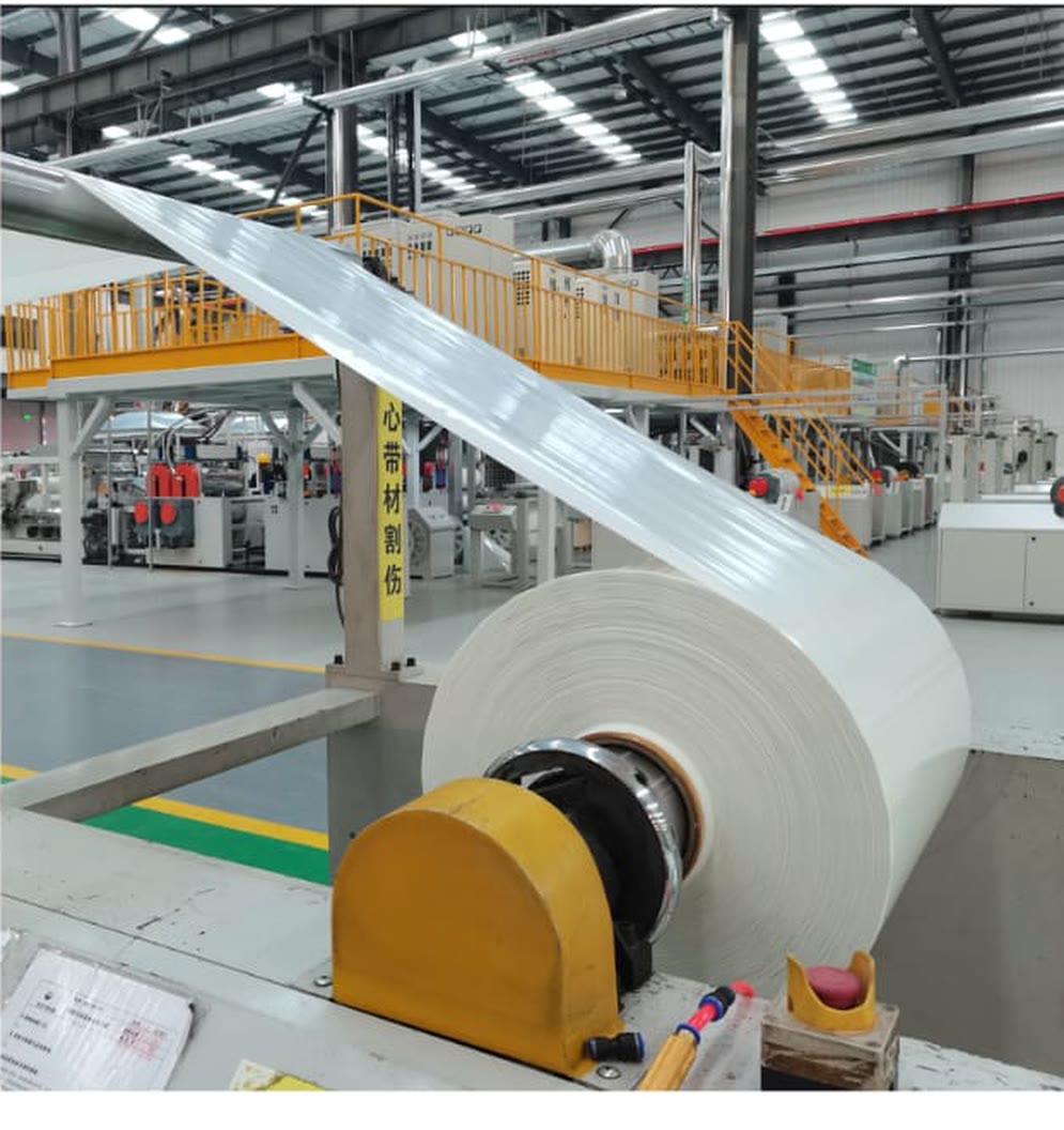
Clear PMMA and colour ABS are co-extruded over a structural core, 1500 mm wide. The colour is in the sheet before the sheet has a shape. There is no film to spray on later.
In PMMA, colour ABS, structural coreOut Colour sheet on the roll
02
Vacuum thermoforming
The sheet is drawn onto the tool and takes finished exterior geometry, up to 1.5 m² in a single shot. Class-A gloss survives the forming step, and that is the property the whole process is built to protect.
In Colour sheetOut Formed Class-A skin
03
Long-fibre injection
Chopped glass fibre, 12.5-100 mm, and PU are sprayed directly onto the back of the formed skin. Skin and structure fuse into one part instead of being welded into an assembly.
In Formed skin, glass fibre, PUOut Skin and structure, fused
04
Press, foam, out
One press step consolidates the section, sets rigidity and integrates hardware, with foamed cores where stiffness-to-weight demands them. The hard coat goes on after the panel has its geometry, never before.
In Fused partOut Finished panel, out of the cell
Impregnation and fibre dispersion.
Everything downstream (tape, laminate, formed panel) is decided in the moment the fibre is wetted. These two lines are the ones the company was built around.
Melt impregnation, mastered.
Continuous glass fibre is fully wetted out in thermoplastic resin on our own impregnation line. Full wet-out is what makes a tape behave like a structure rather than a laminate, and it fixes every property downstream of it.
Uniform dispersion, down to 0.15 mm.
Fibre-dispersion control produces continuous unidirectional tape at 0.15 mm with no clumping. Uniform distribution is what gives a whole panel the same stiffness, not just the coupon cut out of it.
EP: the same backbone, in volume.
The impregnation line also feeds the EP interior-trim platform, in mass production with major Korean manufacturers since 2021. Li:ma and NEXKIN are built on a process that already runs at production rate.
Structure without the steel.
Li:ma pairs continuous-fibre UD-Tape with honeycomb-core laminates for battery covers, underbody shields and FEM carriers. One-shot formed parts up to 1.5 m², already in mass production.
45%
Lighter than the steel part it replaces240MPa
Tensile strength1.5m²
Largest area formed in one shot100%
Thermoplastic, recyclable at end of lifeWhere the fibre points, the panel is stiff.
A Li:ma laminate is unidirectional tape laid at 0°, ±45° and 90° around a honeycomb core. Because the tape is continuous and the matrix is thermoplastic, the stack is consolidated under heat rather than cured, which is why the finished part can be formed in one shot and recycled at end of life.
Ply angles are set against the load case, so a battery cover and an underbody shield are the same material system with different books of tape.
UD-Tape grade data
Order-ready laminate specs| Matrix | Thicknessmm | Areal weightg/m² | Glass fibrewt% | Tensile strengthMPa | Tensile modulusGPa | Strain at break% |
|---|---|---|---|---|---|---|
| PPFlagship | 0.31 | 518 | 70.8 | 1,070 | 40.6 | 3.6 |
| HDPE | 0.31 | 485 | 63 | 860 | 31 | 2.8 |
| PA6 | 0.34 | 560 | 55 | 730 | 31 | 2.6 |
Representative published grade data to ASTM D5630, D3039 and D790. PP grade density 1.67 g/cm³. Request the full TDS through LYN for certified values.
The skin that is never painted.
A Class-A exterior surface has always been sprayed. NEXKIN is the process window that makes one straight out of the mould. The reason it took this long is a coating order that everyone else got wrong.
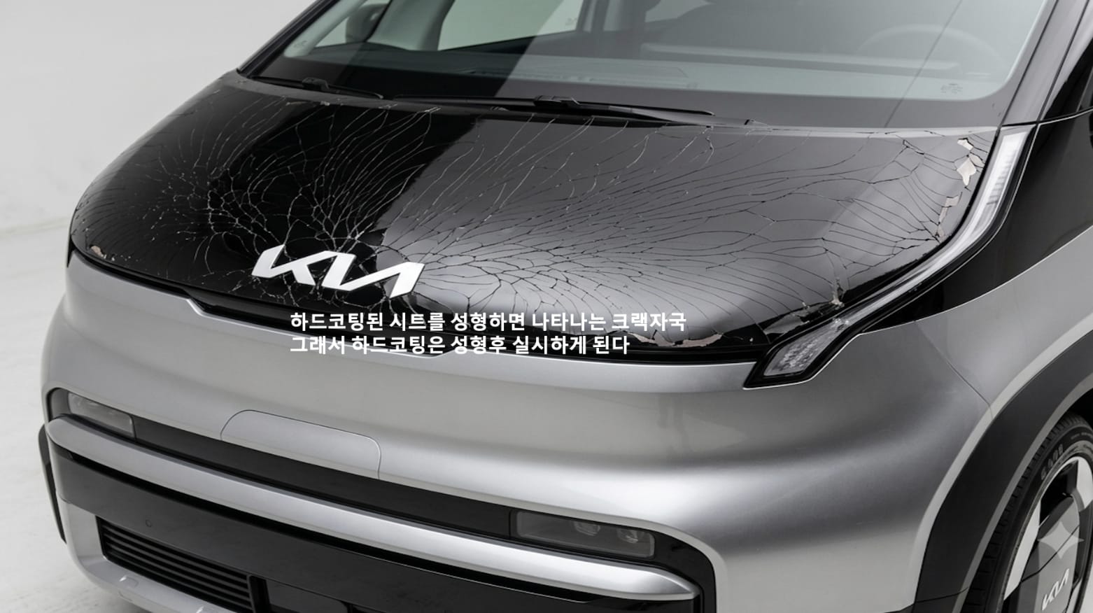
Hard-coat first, and it cracks.
Apply the hard coat before forming and it fractures the moment the sheet is drawn. NEXKIN’s answer is in-line hard coating engineered for post-form integrity: the coat goes on after the panel has its geometry, inside the same line, in a process window the industry had written off as unrunnable in production.
One sheet. Colour, gloss and structure.
Three layers are co-extruded into a single sheet, formed, and backed with structure in the same cell. There is no primer, no basecoat, no clear coat and no oven, so there is no paint shop to build, heat, ventilate or report on.
3layer
Clear, colour and structure in one sheetCF 85-90
Combine Factor: Class-A appearance, no paintGlossy and matte available70%
Less mould investment than steel stamping40-50%
Less process energy than painted steel40-60k
Units/yr where paint-free forming pays back92%
Of material sourced in KoreaAbout 40% below imported cost
Verified, not claimed.
A surface with no paint film on it has to answer two questions: is every part right when it leaves, and does it stay right outdoors. Both are tested rather than argued.
Every part, inspected inline.
Inspection is not a sampling station at the end of the line. It runs over the line itself, on all of production, and catches defects down to a tenth of a millimetre before a panel ever leaves the cell.
- 4K industrial cameras
- Imaging
- IR and multi-angle LED
- Illumination
- AI defect classification
- Decision
- 100% of production
- Coverage
0.1mm
Smallest defect caught by inline AI vision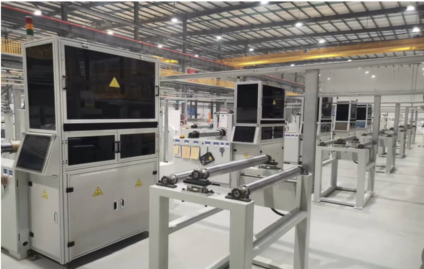
Durability, under the conditions that kill paint.
- Bird dropping and acid variants, high temperatureNo discolorationPass
- Thermal shock and IR-lamp heatingMinimal permanent deformation, no interference or damagePass
- Two years outdoor exposure, Mohave desert conditionsNo discoloration, no gloss changePass
Internal qualification programme. Full test reports available on request.
Lines we built ourselves.
From UD-Tape to a finished exterior panel, the paint-free production lines are in-house builds rather than bought-in cells, which is why the process window can be changed for a part instead of the part being changed for the process.
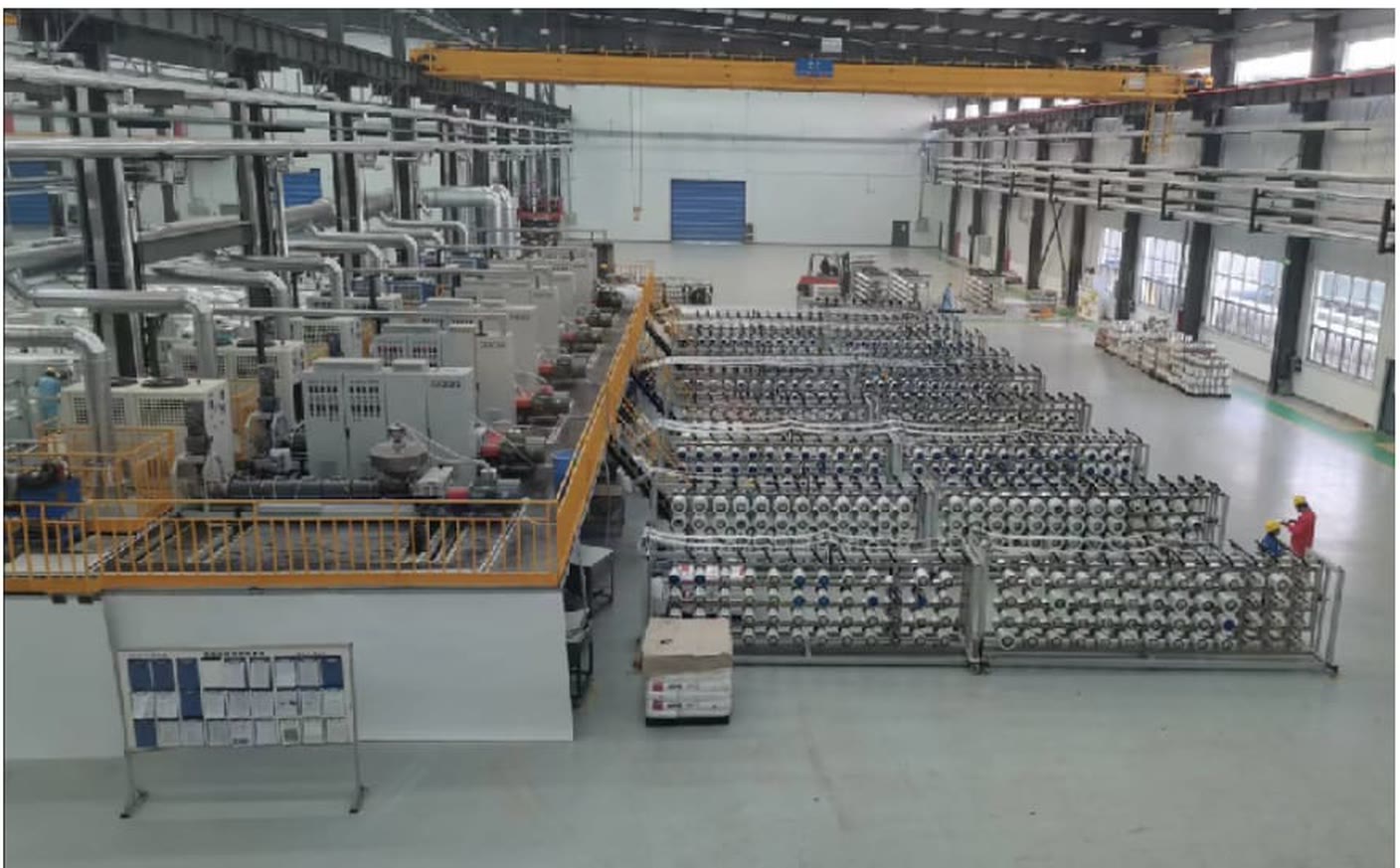
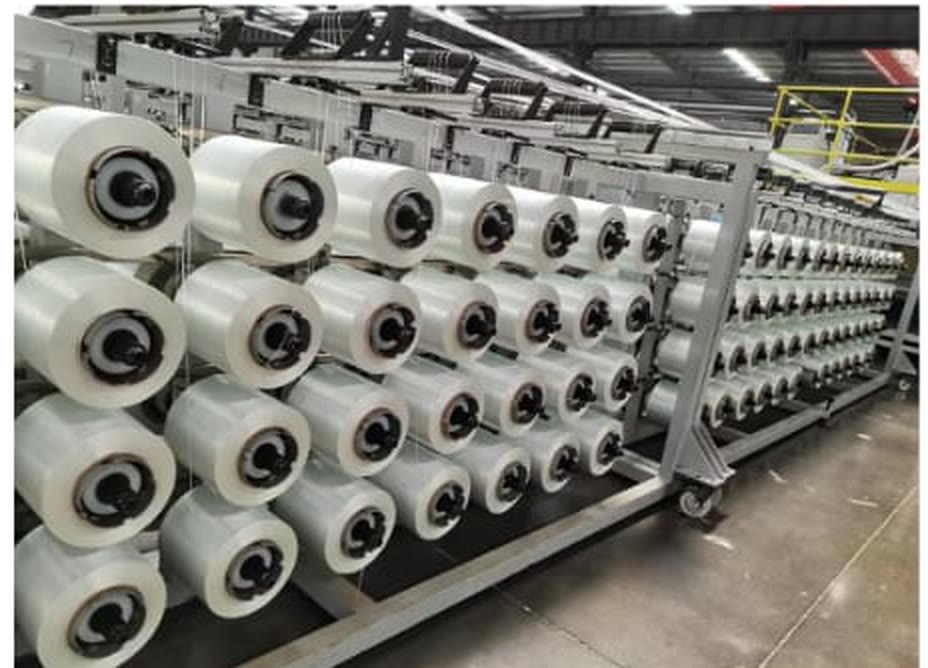
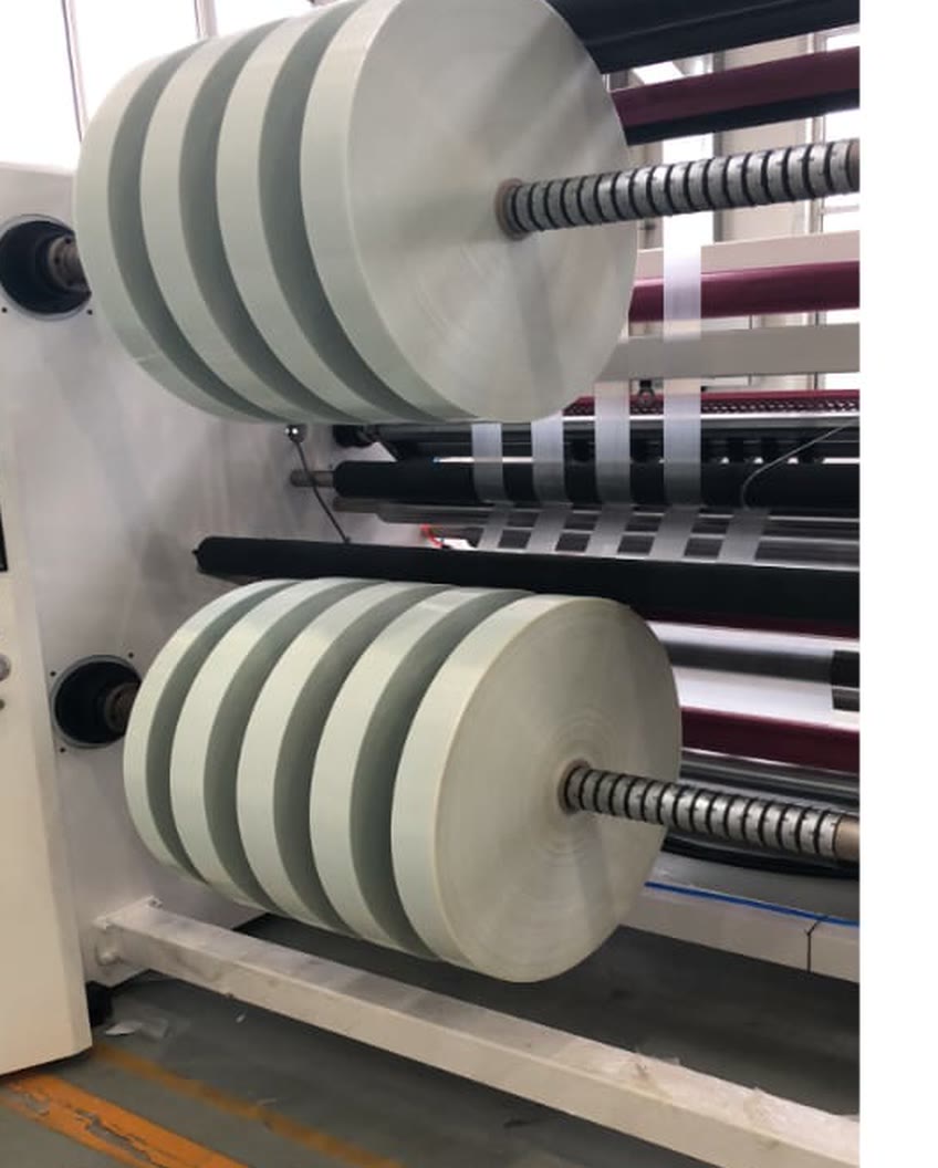
- World’s largest installed UD-Tape capacity
- Produced with CIMC-QCCC.
- 0.15 mm continuous tape
- Ultra-thin unidirectional tape, produced continuously rather than in batches.
- 1500 mm colour sheet
- Co-extruded PMMA / ABS sheet, wide enough for exterior skins.
A platform partner, not an order taker.
OEMs no longer shop for materials alone. The legacy chain (OEM, material maker, Tier-1 molder, each siloed) finds defects late and competes on price only. The alternative is a five-stage integrated solution that optimises unit cost, compresses development time and de-risks tooling revisions and volume ramp-up.
Material and design
Material-driven integrated design: digital material cards carrying temperature, speed and moldability data, plus multi-material composite simulation. Material behaviour and geometry are decided together, and that is where the weight comes out.
Analysis
High-fidelity CAE instead of trial and error: molding-condition prediction, impact, safety and durability forecasting, and post-molding springback correction before a tool is cut.
Forming
Smart molding: the material and the process shipped as one package. 30% off tooling lead time, 50% off ramp-up time.
Production and feedback
In-mold sensors detect defects at the source and live quality data feeds fine-tuning back into the cell. A digital thread keeps full-process traceability, lot by lot.
| Dimension | Legacy · sequential | Compositer · integrated |
|---|---|---|
| Scope | Material only | Module and data |
| Value | Cost cut | Total solution |
| Decisions | Reactive | Proactive |
| Position | Vendor | Strategic partner |
We speak your simulation stack.
Material cards and forming-simulation support drop into the workflow you already run, from concept stiffness to crash. Send a part, get a forming study back.
What you send
- 01Part geometry: STEP, or whatever surface exists today.
- 02The load cases and targets it has to meet: stiffness, impact, mass.
- 03Programme volume and timing.
What comes back
- 01A digital material card for your solver: temperature, speed and moldability data.
- 02A forming study: molding-condition prediction and post-molding springback correction.
- 03Impact, safety and durability forecasting on the formed part.
- 04A weight and stiffness comparison against the steel part it would replace.
The configurator returns a simulated comparison in your browser. A forming study is run by the engineering team and comes back by email.
Datasheets and compliance.
The published grade data, safety documentation and a released mill test report. Certified values for a specific lot come with the RFQ.
Technical datasheets
- PP+GF60Polypropylene UD tape, 60% glass fibreISO test standard · blackPDF · 540 KB(opens in a new tab)
- PP+GF62Polypropylene UD tape, 62% glass fibrePDF · 175 KB(opens in a new tab)
- PP+GF68Polypropylene UD tape, 68% glass fibrePDF · 612 KB(opens in a new tab)
- PP+GF70Polypropylene UD tape, 70% glass fibreISO test standard · blackPDF · 541 KB(opens in a new tab)
- PA+GF55Polyamide UD tape, 55% glass fibreBlackPDF · 270 KB(opens in a new tab)
- PA+GF70Polyamide UD tape, 70% glass fibreISO test standard · blackPDF · 250 KB(opens in a new tab)
- CFRTContinuous-fibre reinforced thermoplastic laminatePDF · 89 KB(opens in a new tab)
- HoneycombHoneycomb-core sandwich panelPDF · 643 KB(opens in a new tab)
- PP 0.6 mmTwin-layer PP sheetPDF · 216 KB(opens in a new tab)
- EVAEVA bonding filmPDF · 536 KB(opens in a new tab)
Every claim has a document.
The published datasheets sit in the library above. For the rest — certified lot values, or a forming study run on your own part geometry — ask the engineering team directly.